DIY
Tesla Model S Front Camera Touchscreen Switch Kit
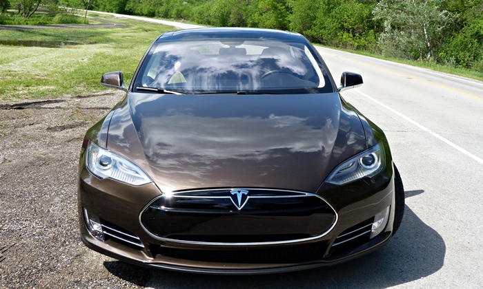
Tesla Model S Front/Rear Camera Touchscreen Switch Kit
The Tesla Model S Front/Rear Camera Touchscreen Switch Kit provides a high-definition front camera view on the factory Tesla Model S touchscreen. The kit utilizes a factory Tesla rear camera that’s discreetly mounted onto the front of the vehicle and provides the same wide angle of sight and high-definition resolution as the rear camera. The camera is connected to a switch that makes it possible to easily alternate between rear to front view when parking your Model S.

With the camera mounted to the front of the Model S, the need for front parking sensors is eliminated. The Tesla Model S Front Camera Touchscreen Kit is ideal for owners who bought early versions of the Model S which were not equipped with parking sensors, as well as late Model S owners who seek an extra measure of visual protection beyond what’s provided by the factory parking sensors.

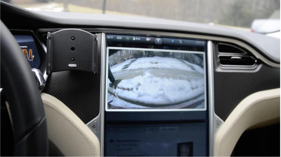
The kit includes the PCB switch itself and all components to make it operational, including a wireless remote control that can be synched with the Tesla HomeLink feature. Switching from rear to front view can be done via the large 17″ factory touch screen. The kit also includes an OBD2 connector that offers a simple way to provide the necessary 12v power and ground connections to the switch.
Installation of a fully operational Front/Rear Camera Touchscreen Switch requires that buyers also purchase the following separately:
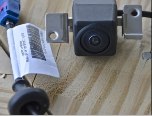
- Tesla rear camera, part #1006773-00-E. The camera can be ordered from any Tesla Service Center for approximately $350.
- A cable set to connect the front and rear cameras to the PCB and touchscreen. The cable set can be purchased from Superbat, a Chinese cable manufacturer, and includes three cables: one long cable for connecting the front camera to the switch and two short cables for connecting the rear camera to the switch and the switch to the touchscreen cable. The kit is $54.50
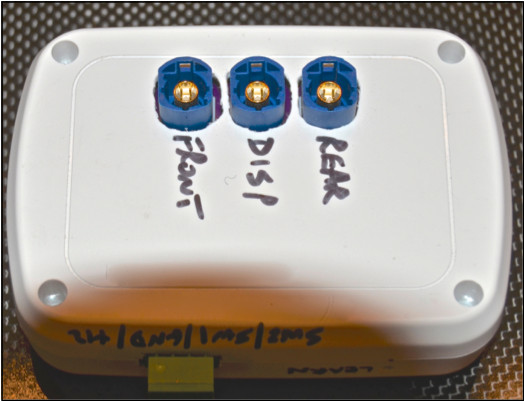
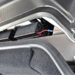
The camera switch PCB case is mounted in the space behind the driver’s side dashboard, which is accessible by removing the small triangular flap on the left end of the dash.
The switch is plug-and play and full installation instructions with photographs are be provided with each kit. Installation will be fairly easy for experienced DIY types and very easy for any aftermarket installation shop.
The pre-production Front/Rear Camera Touchscreen Switch kit price is $225. This price is based on an initial production run of 100 kits and order for at least 50 kits. If a higher number of orders is placed the price will decrease. For example, for 100 orders the price would fall to about $125.00. But for only 25 orders the price would rise to about $450.00. Orders will be taken until Saturday, April 5, 2014 . The final price will be based on the number of pre-production orders actually placed by that time. Production of the PCBs will begin at that time and shipment of orders will begin around the beginning of May. If the final price is lower than the pre-production cost of $225, refunds will be made before shipment. On the other hand if the final price is higher, an additional payment will be required before shipment.
Installation
Parts Required
- Tesla Model S Front/Rear Camera Touchscreen Switch Kit
- Tesla rear camera: Part # 1006773-00-E (available from a Tesla Service Center)! OBD2 connector (provided with the camera switch kit)
- Tesla Camera Cable kit. Available from RFsupplier.com
- Add-a-Fuse (optional depending on 12v power source selected)
- One 5-amp mini auto fuses (optional depending on 12v power source selected)! Optional front license plate mounting bracket (available as option with Camera switch kit)
- 10 feet red 20 gauge wire
- 5 feet black 20 gauge wire! 3M double sided auto tape
- Clear silicone adhesive (Goop recommended)
Installation Tools
- Wire cutters
- Wire stripper
- Hack saw or Dremel tool with cut-off disc
- Plastic pry tool
- 1/8” four foot dowel or rod
- Soldering pencil or gun
- Solder
Choosing a 12v Power Source
To begin you must choose one of the following options for powering the camera switch.
- Powered on and off with the car (option 1)
This option powers the camera switch on when you sit in the driver’s seat and engage Drive or Reverse. The camera switch powers off when you exit the car. This method preserves 12v battery power when the car is parked. There are two options for this “switched” power method. Both methods are described in more detail in the instructions below.
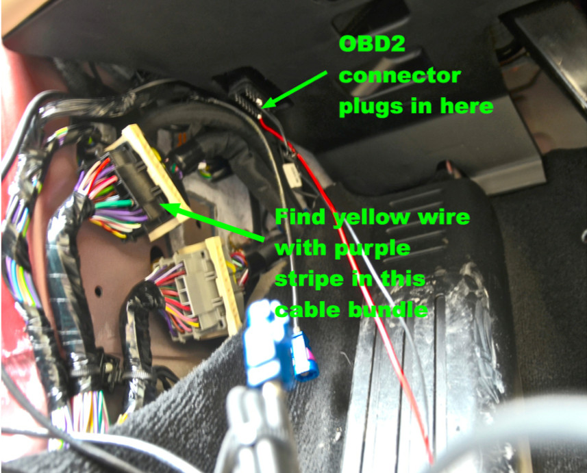
- Using a PosiTap tap power from the yellow wire with purple stripe in one of the three wire bundles behind the driver’s side kick panel. This method is highly recommended, as the fuse tap solution below requires running a long lead from the #3 fuse box through the fender channel with the camera cable into the driver’s door jamb area.
-
Using an Add-a-Fuse and a 5 amp mini fuse, tap fuse #75 in fuse box #3.
- Always powered always on via the OBD2 connector (option 2)
The OBD2 connector provided with the camera switch kit provides both a 12v and ground connection. With this method the camera switch is always on and thus uses power from the 12v battery. If your car will be parked for long periods of time (10 days or longer) without access to a charger, do not not use this method.
Mounting the Front Camera
- Option 1: Without front license plate
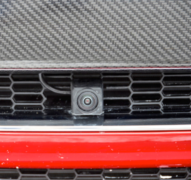
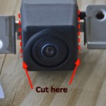
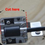
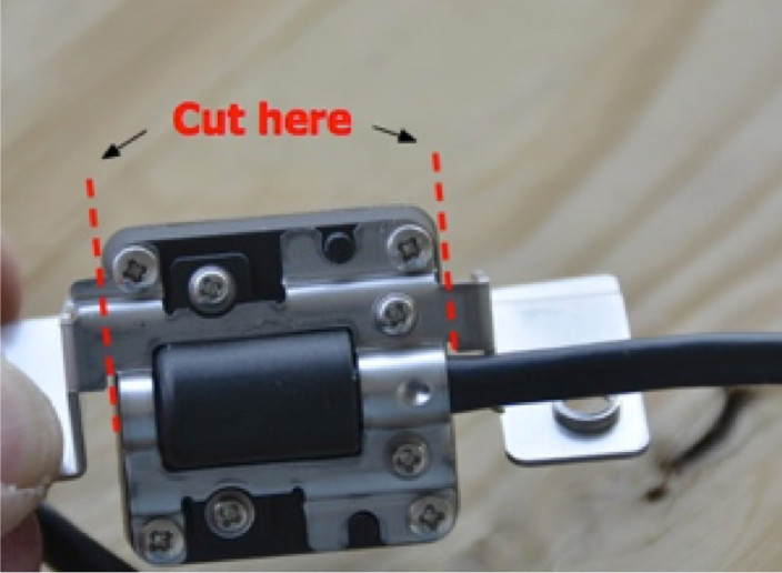
The camera mounts on the center upper front grille just under the nose cone. While the photo shows some of the grille elements cut out, no alterations to the grille are necessary.To mount the camera in this position, the two wings on the metal camera mounting bracket must be first cut off. Using a Dremel tool with a cut off disc or a hack saw, cut the mounting bracket as indicated in the photos below.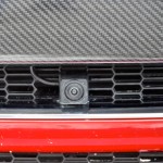
The camera is now ready to mount and the cable routed. Follow these steps:

- Remove the nose cone.
- Remove the right side plastic frunk trim.
- Locate the center point of chrome strip in front of the upper grille under the nose cone.
- Attach the long Chinese camera cable to the end of the short camera cable. Make sure the connectors lock into place.
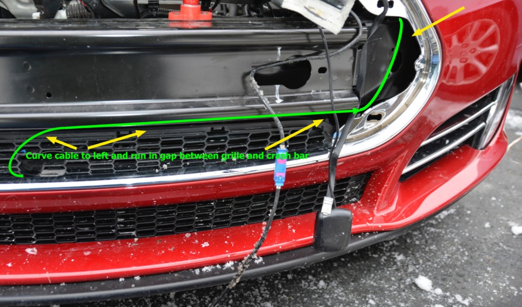
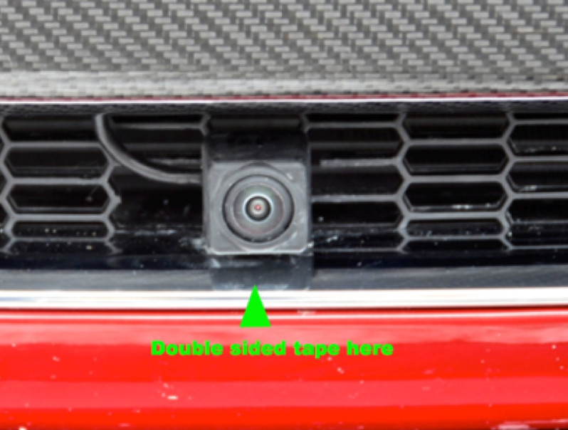
- Cut a small square of 3M double sided auto tape the size of the camera bottom and attach it on the chrome strip as shown in the photo. With the camera cable to the left and curved up, place the camera loosely on the tape. Then push the cable into the small gap along the top of the grille running it all the way to the opening on the left of the chrome surround/mount for the nose cone.
- Once the cable has been run, place a generous dab of clear silicone adhesive on the back of the camera and press it firmly into place against the grille and on top of the tape. Make sure it is properly aligned. Then use some duct tape to hold it in place while the adhesive dries (about an hour).
- Run the cable up into the driver’s side of the frunk, near the headlight. Thread it through the openings behind/around the right side of the nose cone near the fender channel.

- Option 2: With standard Tesla front license plate mount
For this mount the wings must remain on the camera. Do not cut them off. Screw the camera mount bracket on the bottom center of the license plate frame. Mount the camera on the bracket using the two mounting screws provided with the camera itself. Route the camera cable following the same instructions for ‘Choosing a 12v Power Source’. - Option 3: With low-mount front license plate
For this mount the wings must be cut off the camera, as described above. If you have a low- mounted plate frame, mount the camera in a position that provides an unblocked view forward over the plate frame. We recommend mounting it just under but not touching the nose cone. Route the cables as described in Option 1.
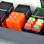
Powering the Camera Switch with Fuse #75 in Fuse Box 3
At this point if you have decided to use fuse #75 to power the switch, see the photos above and follow the steps below. If you’ve decided to power the switch using one of the other options skip to the next step, ‘Connecting Camera Switch and Powering with Other Options’.
- Pry the cover off fuse box #3
- Locate fuse #75 (see photo above)
- Remove the 5 amp fuse in #75 and insert it in one of the two slots in the Add-a-Fuse
- Insert another 5 amp fuse in the other slot!
- Strip about 1/4 insulation from a 6 foot length of 20gauge red wire
- Crimp the stripped end into the Add-a-Fuse
- Insert the Add-a-Fuse into fuse slot #75
- Using a Dremel tool cut a 1/8 slot in the front side of the fuse case cover so the red wire can exit the fuse case.
- Thread the red wire carefully along the upper part of the frunk, running it under appropriate components that will hold it loosely in place and placing the end loosely in place near the fender channel and the end of the camera cable.
Connecting Camera Switch and Powering with Other Options
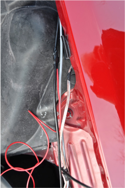
- From the driver’s upper door jamb find the two channels that go into the fender area. Push a 1/8” dowel through the larger, lower channel from the door jamb side. Then locate the end of the dowel from the frunk side. You may have to try several times to insert the dowel through this space, so be patient.

- When the dowel is through the fender channel space, tape the camera cable to its end, taking care to tape over the cable connector so it won’t get caught when you pull it through the fender channel space. If you’re using the fusecase 12v power source, tape the red wire tightly behind the camera cable connector. Then carefully pull the cable and red wire through. The connector will just fit the space, so be careful pulling it through.
- When all has been pulled way through, leave 4-6 inches of slack on the frunk side so the wires/cables are not under stress.
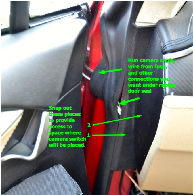
- Now take the ends of camera cable (and optional fuse 12v red wire) and pull the them under the rubber door seal. To do this you’ll have to pull the rubber seal away from its seating on the door jamb. Pull the cable and wire all the way through, leaving the 4-6 inches of slack on the frunk side.
- Snap out the driver’s side kick panel, starting with the narrow end along the door sill and work it loose up to the end near the dead pedal. At the same time, using a plastic pry tool, remove the small triangular black piece from the end side of the dash, placing it carefully on the floor of the car so that it doesn’t not stress or brake the wire connection to the key fob sensor on the back side. One this piece is removed, carefully snap out the small vertical plastic piece against the door jamb.
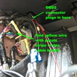
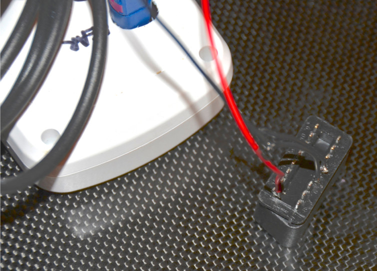
- If you’re using the OBD2 connector to provide 12v and ground to the camera switch, at your work bench solder a 16 “ piece of black 20 gauge wire to pins 4&5 on the connector and a 16” piece of red wire to pin 16 If you’re using the yellow purple stripe wire to power the camera switch you’ll only need to solder the ground connection to pins 4&5 on the OBD2 connector.
- If you’re using the yellow/purple wire as the switched source of 12v power to the camera switch, locate the yellow wire with purple stripe in one of the three wire bundles and connect a PosiTap to it. Attach a 12” length of 20 gauge red wire to the other end of the Posi-Tap. It may be easier to locate the wiring by first finding it one of the white multiple pin connectors and tracing it back. As noted, with this connection method you will only need the OBD2 connector for ground.

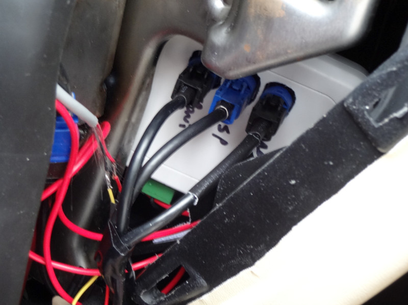
- Now locate the blue rear camera and touchscreen connector near the wire bundles. The connectors have small pinkish red tops. Press on the tab to disconnect them. Having pulled the front camera cable and connector through to the kick panel area, you will now have three connectors to plug into the camera switch PCB case: front camera, rear camera, and touchscreen. To identify the front camera connector, place a small piece of electrical tape around the front camera cable. This will be important when you plug the cables into the PCB case.
- Now, depending on which 12v sources you’re using, cut the connecting wires to the appropriate length needed to fit the the camera switch PCB case into the space behind the dash that removal of the side panel made accessible. Then make the 12v and ground connections to the green screw connector part of the camera switch PCB case.
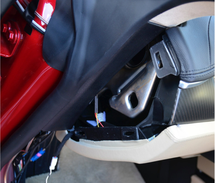
- With the 12v and ground connections made, slip the PCB case into the space behind the dash make sure the blue plugs are accessible from the open size. The case will slide around but when the camera and touch screen connections are made that won’t be a concern.
- Now connect the cameras and touchscreen to the PCB case. For easier connections, study the connectors to make sure the alignment is correct, the using your left hand inside the space behind the dash plug in the connectors, making sure the tab is snapped in place so they can’t come loose.
- Now, using the remote that came with the camera switch kit, test the system. Sit in the driver’s seat and put the car into reverse. The rear image should appear on the touchscreen. The videos below show the switch in operation.
- Now push button A on the remote. For 2-3 second the touchscreen will turn gray and the words “Camera Unavailable” will appear. After this short lag the front camera image will appear. Then push and hold B. With the same pause, the image will switch to the rear.
- The remote functions are these:
- A: Front/rear toggle
- B: When held will always force camera to rear if on front or stay on rear if on rear.Next if you want to control the camera switch with Homelink, following the standard HomeLink programming instructions on the touchscreen, program HomeLink with the remote. Test that the Homelink commands work properly.
- With everything tested and operational, careful place the camera and touchscreen cables in place. You likely will have excess cable from the front camera. Lifting the rubber door seal pull the excess through so it’s hanging loose on the outside of the rubber seal. From the frunk side pull the excess through so the cable lies tightly against the door jamb. Coil any extra on the frunk side and tape it into a convenient space where it will be hidden and out of the way.
- Test the operation of the camera switch on more time. Then reinstall the various panels you removed in the cockpit and frunk.
Where to Buy
Back in 2019, YouTuber Simone Giertz, the self-proclaimed “Queen of Sh*tty Robots,” created a one-off Tesla Model 3 build that took the automotive world by storm. Fondly dubbed as “Truckla,” Giertz noted that the vehicle was actually her dream car — as crazy as that may sound.
Now almost four years later, the YouTuber posted an update on Truckla. And just like every other big project that one probably started, Giertz stated that she actually stopped working on Truckla when the vehicle was about 80% complete. The car is driving though, but a lot of stuff was not really working very well.
Thus, for her Truckla update, Giertz shared how most of her Model 3 pickup truck conversion was essentially completed. Truckla got a lot of detailing done, she got a slight lift, and she now has a functional tailgate. One has to admit, Truckla’s tailgate is pretty darn cool.
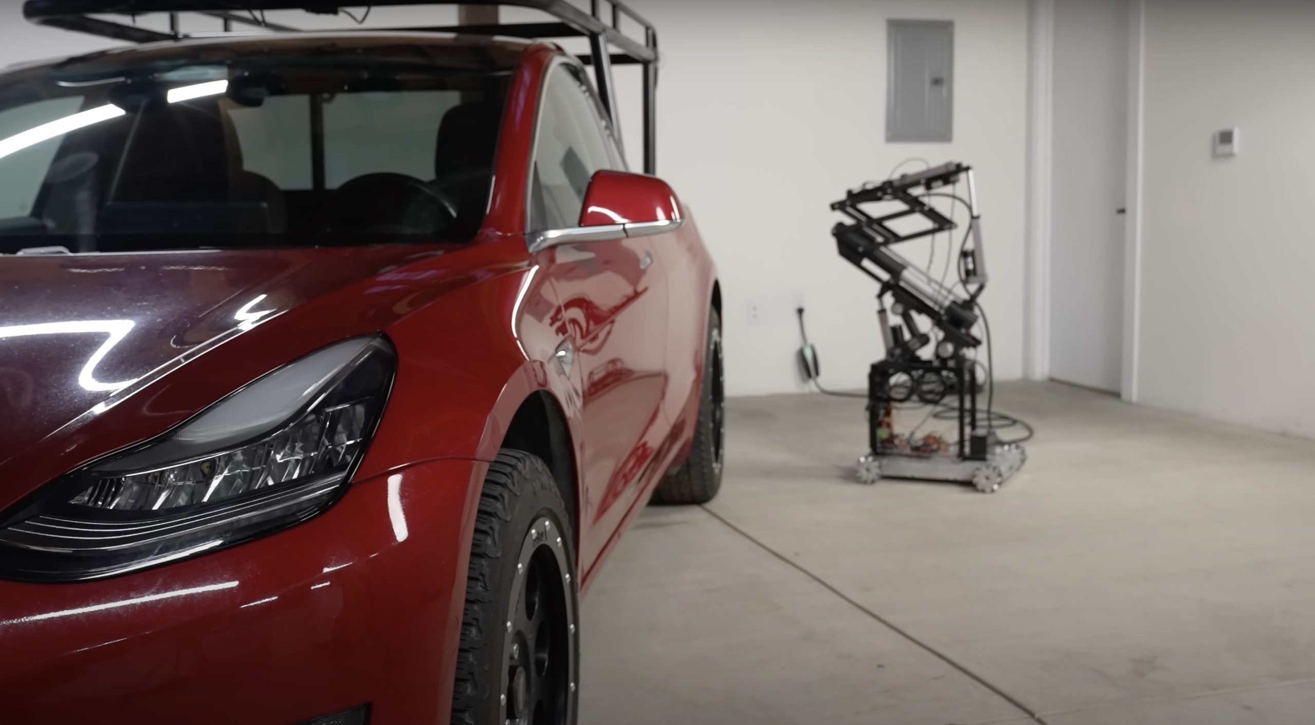
The “Queen of Sh*tty Robots” also opted to give Truckla a friend in the form of an automatic robot charger. Unlike Tesla’s rather interesting snake charger from years past, Truckla’s charger would come in the form of a rover, thanks to her friends at robotics platform Viam. Giertz aptly named Truckla’s robot charger friend “Chargela,” which is an appropriate name for such an invention.
Also true to form for Giertz, Chargela’s first encounter with Truckla was just a tiny bit awkward. One could say that Chargela may have just been a little bit nervous on his first try without human hands helping him. Most importantly, the system did work, so Giertz would likely keep using Chargela for her Model 3 pickup.
Teslas are very tech-heavy vehicles, so projects like Giertz’s Truckla are always remarkable. The fact that the Model 3 works perfectly fine despite having a good chunk of it cut off and turned into a pickup truck bed is mighty impressive any way one looks at it. Overall, Truckla will always be one of the coolest Tesla DIY projects to date, so any updates about the vehicle are always appreciated.
Truckla’s nearly four-year update can be viewed below.
Don’t hesitate to contact us with news tips. Just send a message to simon@teslarati.com to give us a heads up.
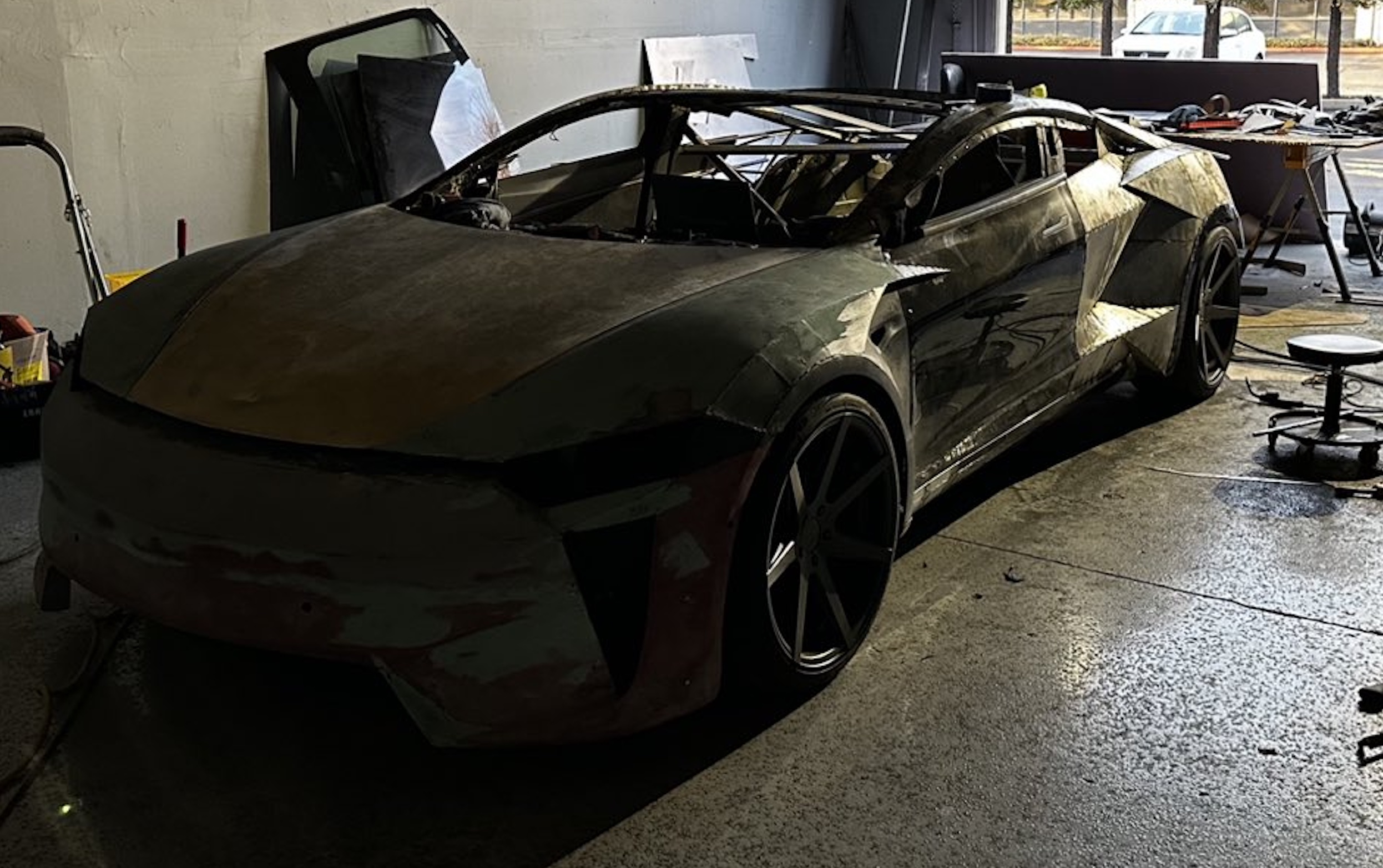
A Tesla owner is taking his hobby and love for electric vehicles to new levels by creating what could only be described as one of the coolest EV-related DIY projects to date. The idea for the project is simple: what happens when you cross a supercar with the Cybertruck? You end up with a two-seater CyberRoadster.
Tesla owner David Andreyev, who goes by the username @Cyber_Hooligan_ on Twitter, has spent the last few months creating a Cybertruck-inspired version of the next-generation Roadster made from a salvaged Model 3 Performance. Starting with a Model 3 Performance is an inspired choice, considering that it is Tesla’s first vehicle that has a dedicated Track Mode.
A look at Andreyev’s YouTube channel, which can be accessed here, shows the meticulous build that the Tesla owner has implemented on the project car. What’s particularly cool about the CyberRoadster is the fact that it’s being built with parts that are also from other Tesla vehicles, like its front bumper that came from a new Model S. Recent videos suggest that the project car’s rear bumper will be from a new Model S as well.
The journey is long for Andreyev, so the completion of the CyberRoadster will likely take some more time. Despite this, seeing the Tesla owner’s DIY journey on such an epic build is more than satisfying. And considering that the CyberRoadster is evidently a labor of love from the Tesla owner, the final results would likely be extremely worth it.
There’s a lot of crazy Tesla modifications that have been done as of late. But some, as it is with a lot of things on the internet these days, have become more silly gimmicks than serious automotive projects. Fortunately, car enthusiasts like Andreyev, who just happen to also love electric vehicles, are taking it upon themselves to create one-of-a-kind EVs that would surely capture the attention of anyone on the road.
Check out the latest video in the CyberRoadster’s creation below.
Don’t hesitate to contact us with news tips. Just send a message to simon@teslarati.com to give us a heads up.
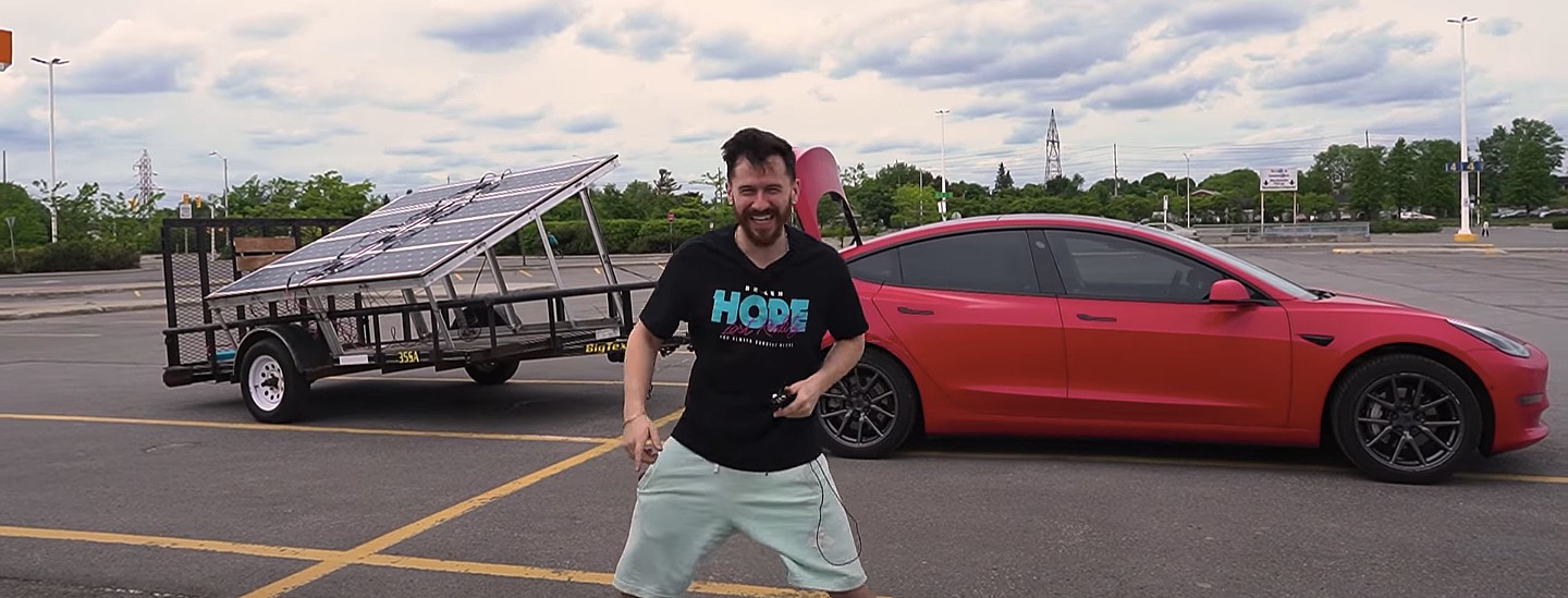
A Tesla owner has demonstrated a rather novel way to charge his Model 3. In a recent video, Sean Callaghan of the ItsYeBoi YouTube channel opted to use a series of off-the-shelf solar panel sheets onto a towable trailer to create a mobile charging unit for his all-electric sedan.
Callaghan planned to use only the sun and the solar sheets purchased from e-commerce platform Wish to charge his Model 3. The solar panel sheets would collect energy from the sun and transfer it to a control panel. The control panels were connected to batteries that would hold the energy—the batteries connected to an inverter, which would then charge the Tesla Model 3.
The entire assembly would provide the Model 3 with about 800 watts of energy on a completely sunny day. However, Callaghan shot the video when weather was overcast, so the entire solar panel trailer build only managed to provide around 300 watts throughout the YouTube host’s test.
To put this into perspective, a 100 volt home wall outlet provides 1.4 kilowatts of power, or 1,400 watts. Therefore, the 300-watt solar panel assembly built by Callaghan was producing less than 25% of the energy of a typical wall outlet. This is pretty marginal compared to Tesla’s 250-kilowatt V3 Superchargers, which provides 250,000 watts, or about 833 times as much power as the makeshift solar panel build.
However, Callaghan’s goal was not to charge the vehicle quickly. He explained the idea came from a previous video where he used a $5,000 Wish-purchased wind turbine to charge his Model 3. He wanted to test the effectiveness and efficiency of the system, which was questionable due to the time it would take to charge the battery fully.
The Model 3 battery pack is 78 kWh, and with Callaghan’s 300-watt system charging his electric vehicle, it would take 260 hours to supply the Tesla’s battery to full capacity.
In the past, electric vehicle enthusiasts have asked Tesla CEO Elon Musk why the company’s vehicles do not contain solar glass roofing, which would charge the car while the owner is driving. Musk has explained that the efficiency of this idea is challenging and likely would not provide an ample amount of range.
When asked about the idea of putting solar panels on the top of Tesla’s vehicles in 2017, Musk responded that the idea was “Not that helpful, because the actual surface of the car is not that much, and cars are often inside. The least efficient place to put solar is on the car.” It also would not be cost-effective for Tesla because “the cost of the panels and electronics, R&D and assembly would never pay for itself in the life of the vehicle, compared to charging from the wall in your garage,” Quartz noted.
That being said, Tesla plans to implement solar panels onto the motorized tonneau of the upcoming Cybertruck. The idea was discussed on Twitter when Musk stated that the optional feature would add “15 miles per day, possibly more” when parked in the sunlight. Also, fold-out solar wings could help capture enough solar energy for 30 to 40 miles a day.
Watch Sean Callaghan’s video of his makeshift solar panel trailer below.
Tesla Model Y prices just went up for the first time in two years

Elon Musk explains why he cannot be fired from SpaceX


