News
Tesla’s liquid-cooled charging connector patent paves way for the Semi’s Megachargers

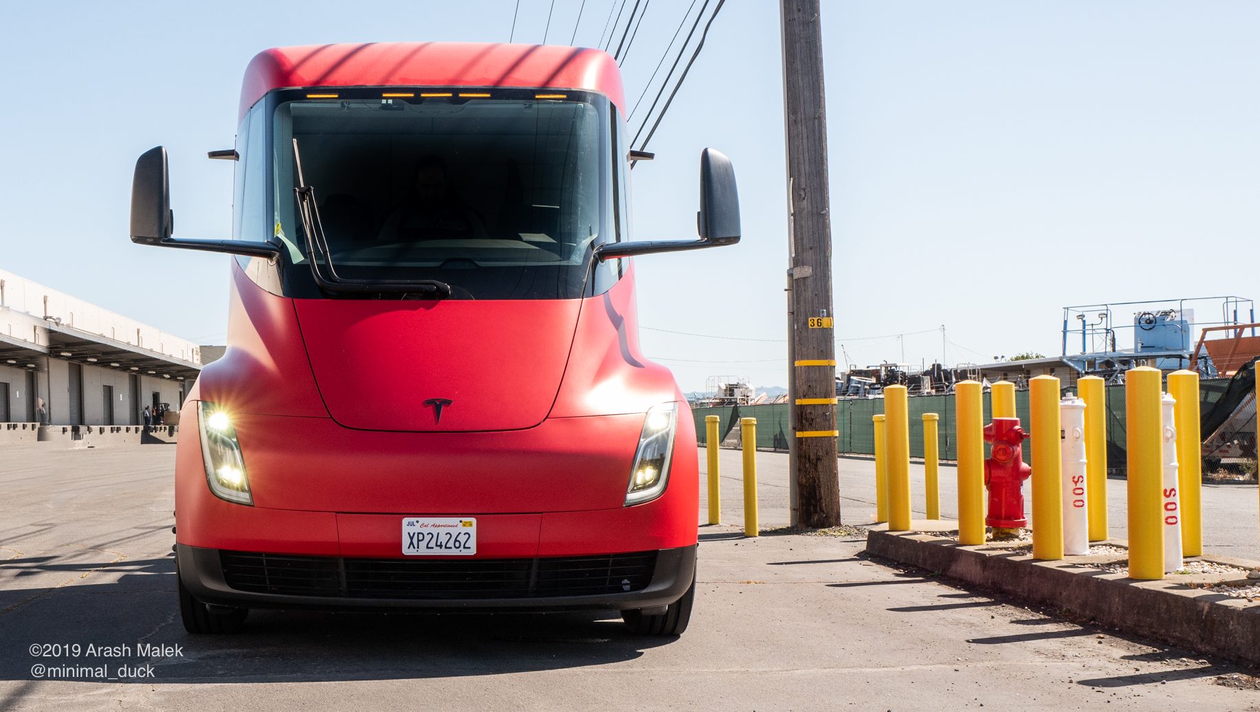
A recently published patent application from Tesla suggests that the electric car maker is continuing in its efforts to improve its already-stellar Supercharger Network. The design outlined in the document, which features a liquid-cooled charging connector, can potentially pave the way for a more ambitious charging infrastructure, perhaps one that can specifically cater to the all-electric Semi’s Megacharger Network.
During the all-electric truck’s unveiling, CEO Elon Musk mentioned that the Semi will be able to replenish as much as 400 miles of range in as little as 30 minutes thanks to a network of Megachargers. Neither Musk nor Tesla provided the specs of the Megacharger during the vehicle’s unveiling, though speculations were high that network might provide a power output that is several times more powerful than the company’s Supercharger V2 Network, which had an output of around 120 kW then (Supercharger V2 stations have since been improved to 150 kW).
Being a large vehicle, the Semi requires a lot of power for its charging needs, involving the rapid transfer of mass amounts of electricity in a very short period of time without encountering any heating issues. This is a key concept outlined by Tesla in its recently published patent, titled “Liquid-Cooled Charging Connector,” which involves the use of a liquid cooling system on a charging connector itself. Tesla describes its concept in the discussion below.
“To transfer energy faster and decrease charging times, the cable and charging connector must be capable of withstanding high current loads. Current charging connectors are limited in the current loads that they can support as their ability to dissipate heat is limited. Thus, there is a need for a new charging connector to solve the aforementioned problems.
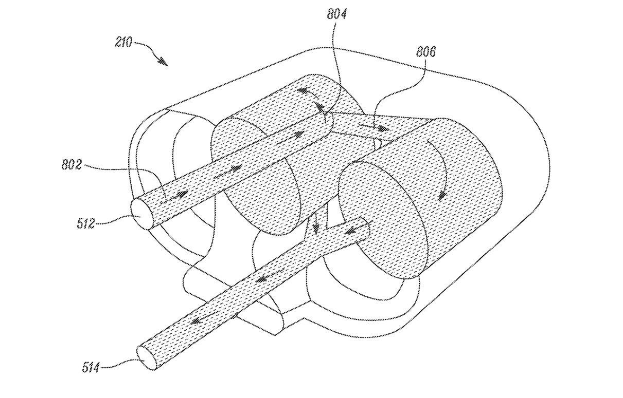
“The present disclosure related to a new charging connector. The charging connector has a first electrical socket and a second electrical socket. A first sleeve is concentrically coupled to the first electrical socket and a second sleeve is concentrically coupled to the second electrical socket. A manifold assembly encloses the first and second electrical sockets and the first and second sleeves, such that the first and second sleeves and manifold assembly create a hollow interior space there between. The manifold assembly has an inlet conduit and an outlet conduit such that inlet conduit, interior space, and outlet conduit together create a fluid flow path.
“Cooling fluid flows through the fluid flow path and cools the charging connector. During operation, the cooling fluid bifurcates into a first fluid stream which flows around the first sleeve, and a second fluid stream which flows around the second sleeve. The first and second fluid streams combine upstream of the outlet conduit. The first sleeve encloses the first electrical socket, and the second sleeve encloses the second electrical socket. The cooling sleeves are made from a thermally conducting material such that heat generated by electrical sockets can be removed by the cooling fluid. In embodiments, this thermally conducting material is a thermally conductive plastic material.”
Tesla notes that its liquid-cooled supercharger connector does not only allow faster charging; it also makes the routing of wires in a charging connector much more efficient. This means that Tesla’s Supercharger connectors could eventually be smaller and more compact despite being capable of greater output. An example of this appears to be hinted at by Supercharger V3’s liquid-cooled cables, which are smaller and more compact than those used in Tesla’s V2 Network.
“Cooling fluid absorbs thermal energy from heat in the electrical sockets 404, 406. Sleeves 410, 412 are made of a thermally conducting, electrically insulating material. Heat from the electrical sockets 404, 406 is transferred to cooling fluid through sleeves 410, 412. After flowing around hollow interior space 416, the first fluid stream 804 and the second fluid stream 806 combine together upstream of outlet conduit 514 and flow outside of manifold assembly 414 through outlet conduit 514. Cooling fluid flowing out of manifold assembly 414 through outlet conduit 514 may be received by a reservoir (not shown) which may provide for heat exchanging arrangements. A heat exchanger may be provided to take away heat absorbed by cooling fluid. After rejecting absorbed heat, the cooling fluid may be recirculated back to inlet conduit 512 for further cooling of charging connector 210.
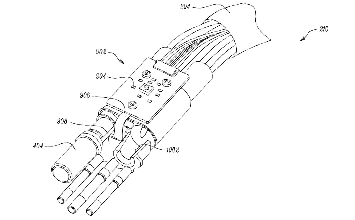
“FIG. 9 shows another component included by charging connector 210. A Printed Circuit Board Assembly (PCBA) 902 is thermally coupled to charging connector 210. In embodiments, PCBA 902 is a two-part structure. A first part of PCBA 904 is coupled to charging connector 210 such that the first part of PCBA 904 sits on top of electrical sockets 404, 406. A second part of PCBA 908 is connected to the first part of PCBA 904 through a rigid-flex PCB construction, or other similar interconnects. The two-part structure of PCB A 902 allows for a more efficient routing of electrical wires of charging connector 210, and overall size of charging connector 210 may be conveniently reduced.”
Tesla’s Superchargers are among the fastest and most expansive electric vehicle charging infrastructures in the auto industry. In keeping with its spirit, the company has made it a point to never stop innovating, as exhibited by the company’s debut and ongoing ramp of its Supercharger V3 Network. This could ultimately pay off for Tesla, whose lead in the electric vehicle race might potentially increase even more.
Such innovations appear to be required of the company, especially with the rollout of ambitious EVs such as the Semi, a vehicle with a different charging infrastructure compared to Tesla’s existing lineup of electric cars. That being said, Tesla nevertheless deserves credit for pushing the envelope and staying on top of its innovations. In the electric vehicle race, after all, a liquid-cooled charging connector could end up making the difference between the fast-charging capabilities of the Tesla Semi and rivals from Daimler and Nikola.
A link to the full text of Tesla’s liquid-cooled charger connector patent could be accessed here.


Investor's Corner
Tesla has a Cybercab problem nobody saw coming
Tesla’s Cybercab line now builds robotaxis faster than Tesla can deploy them, Lars Moravy says.

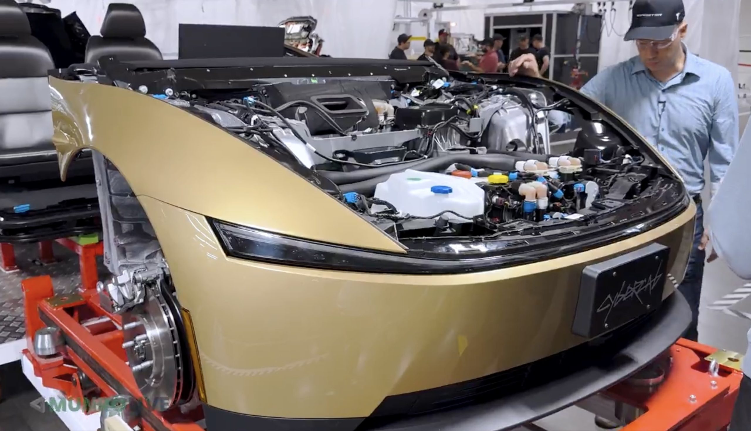
Tesla’s Cybercab line in Texas can now build the two seat robotaxi faster than the company can put it into service, according to Lars Moravy, Tesla’s Vice President of Vehicle Engineering. “We don’t run every day because the line can run so fast. It’s currently outpacing our deployments,” Moravy said in a new Cybercab deep dive from Munro Live. “So, it’s a bit of a race right now. Who’s going to go faster? Right now the manufacturing line’s ahead.”
Tesla’s official Robotaxi account shared a Cybercab analysis video on X on Monday, calling it a “Cybercab engineering deep dive.” Moravy’s comments go further than what he told analysts on the Q3 earnings call last week, when he said the Cybercab line’s listed capacity of more than 125,000 units a year undersells what it can actually run.
The tour shows where that speed comes from. Tesla’s unboxed process splits the Cybercab into front, rear, side and center modules that are built and tested on their own before they meet on a short final line. That final line has just 25 fully automated stations, which Tesla’s team estimated is a fifth to a tenth of what a Model Y needs. The full line is about 78% automated, the framing line is already at 100%, and the layout uses roughly 50% less floor space per vehicle. The stated goal is “100% automation in 10 second cycle time,” or one finished Cybercab every 10 seconds.
Tesla also deleted the paint shop. Only the side modules are coated, and the exterior panels get their color inside the molding machine. Engineers said the car is designed to run at least 500,000 miles, which matters for a vehicle that will spend most of its day carrying riders.
The battery got the same treatment. The Cybercab uses an 88S6P pack of 4680 cells in a steel enclosure, a first for Tesla, with each module potted separately so a single failed module can be swapped instead of the whole pack. Wireless battery management boards replace a wiring harness, and new contactors are fast enough to drop the pyro fuse entirely. Tesla’s battery director graded the pack an A minus, compared with a D for the Model Y structural pack and a B minus for Cybertruck. Up front, the drive unit runs an 11:1 gear ratio versus roughly 9:1 on most Teslas, since the Cybercab does not need a high top speed.
Cybercab engineering deep dive — Robotaxi (@robotaxi) October 26, 2026
The deployment side is now the bottleneck Moravy described. Tesla had more than 50 Cybercabs working the Formula 1 weekend in Austin, and Texas records show 463 Cybercabs registered. Tesla said on its earnings call that Cybercab service will launch in Dallas next month, and Moravy said the company is aiming to get Cybercabs to customers by the end of 2026. Every unit built so far has gone into Tesla’s own fleet since the line moved into volume production in April.
Munro Live also asked when it could get a Cybercab to tear down. Tesla’s answer: “Not yet.”

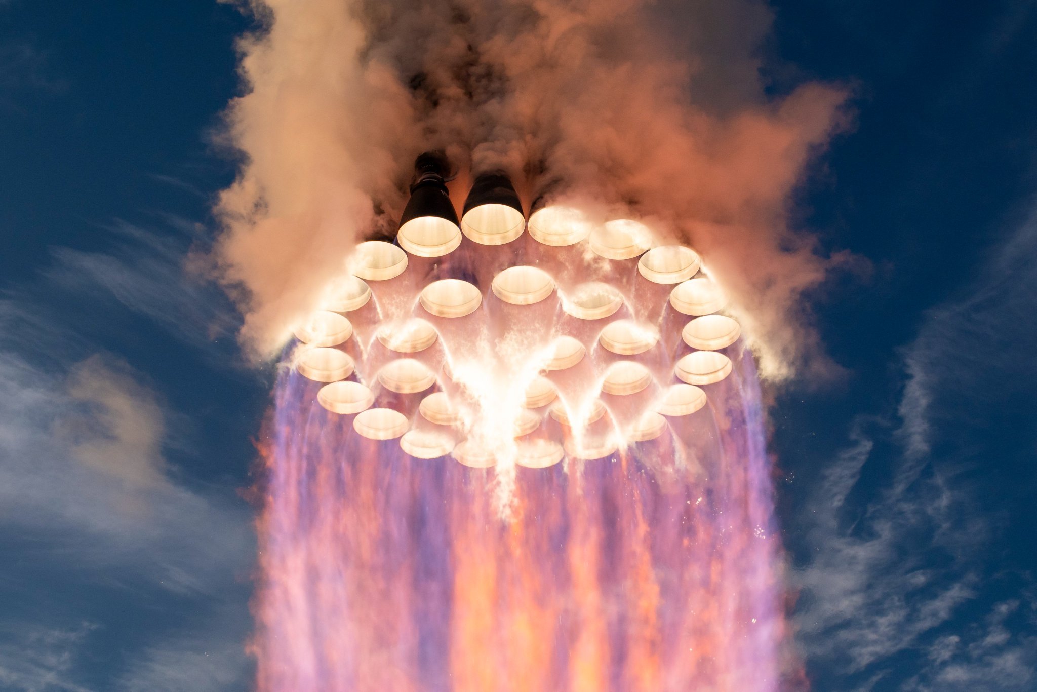
SpaceX’s Raptor engine family has steadily increased sea-level thrust while simultaneously reducing mass, turning iterative engineering gains into substantially higher performance for the Super Heavy booster. CEO Elon Musk shed more light on how powerful Raptor 4 will be, and it’s pretty crazy.
Raptor 1 delivered 185 metric tons of thrust at roughly 2,080 kilograms, while Raptor 2 raised that to 230 tons while cutting mass to about 1,630 kilograms. SpaceX data for Raptor 3 lists a target of 280 tons at 1,525 kilograms (with further reductions in associated vehicle hardware), while operational flight ratings have been cited near 250 tons.
This morning, Elon Musk stated that Raptor 4 is expected to reach 300 tons of sea-level thrust at roughly the same mass as Raptor 3. Across these versions, thrust has risen by more than 60 percent from the first engines while engine mass has fallen, producing a sharp improvement in thrust-to-weight ratio. This is a true testament to how great SpaceX engineering has been:
🚀 Elon says Raptor 4 will make 300 tons of thrust at sea level at roughly the same mass as Raptor 3.
How far Raptor has come:
Raptor 1: 185 tf, 2,080 kg
Raptor 2: 230 tf, 1,630 kg
Raptor 3: 250 tf, 1,525 kg
Raptor 4: 300 tf33 on Super Heavy = ~9,900 tf, nearly 3x Saturn V https://t.co/HQDswZhyvL
— TESLARATI (@Teslarati) October 26, 2026
With 33 engines on SuperHeavy, the jump from earlier versions to a 300-ton Raptor 4 would produce roughly 9,900 metric tons of total liftoff thrust, nearly three times the Saturn V’s approximately 3,400 metric tons from its five F-1 engines.
This is not just a larger number on a data sheet, either, as sea-level thrust is the force available the moment the vehicle leaves the pad. This is when it is heaviest and still deep in Earth’s gravity well and dense atmosphere.
Higher levels of sea-level thrust directly improves the initial thrust-to-weight ratio of the full stack. A higher ratio produces faster acceleration off the pad, which shortens the time the rocket has to spend fighting gravity, and gravity losses during the first minute or two of the flight are a major drain on total available delta-v. Every second shaved off of that early climb preserves more propellant energy for reaching orbital velocity or for carrying extra payload.
Because Super Heavy’s engine count is constrained by vehicle diameter and packing density, increasing thrust per engine is the most straightforward way to raise total liftoff performance without redesigning the booster structure or design.
The same-mass target for Raptor 4 is equally important. Holding engine mass roughly constant while raising thrust improves the engine’s own thrust-to-weight ratio and reduces the structural and propellant mass fraction that must be carried solely to support the engines.
Earlier Raptor iterations also simplified or eliminated extensive vehicle-side hardware such as heat shields. These gains compound: more force for less installed mass leaves additional capacity for propellant, payload, or operational margins such as engine-out capability.
For Starship’s architecture, the practical effects are large. Greater liftoff thrust supports heavier vehicles, larger propellant loads, and higher payloads to low Earth orbit, figures SpaceX has targeted in the 100-plus-ton reusable range. That capacity underpins orbital refueling, lunar missions, and eventual Mars cargo and crew flights.
Continued growth in sea-level thrust therefore tightens the gap between theoretical rocket performance and the high flight rates and reusability needed to make large-scale space transport practical.
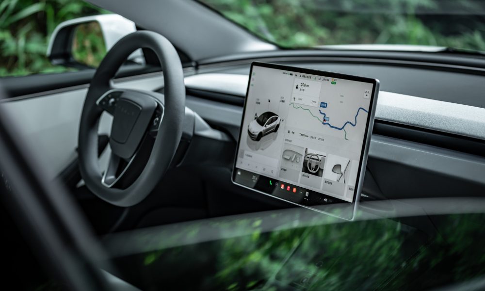
Tesla has expanded its Tesla Assisted Driving (TAD) suite to its tenth European country, as Latvia joined a growing list of European Union member states authorizing the company’s advanced driver assistance technology.
Tesla Europe announced this morning that the system is now approved in Latvia, with a software rollout to begin soon.
The approval and rollout follow recognition of a provisional European type approval originally granted by the Netherlands’ RDW authority on April 10.
🚨 Latvia has just received approval for Tesla Full Self-Driving (Supervised)
This is the 10th country in the EU to gain approval:
1. Netherlands — 10 April 2026 (original RDW approval)
2. Lithuania — 20 May 2026
3. Estonia — 29 May 2026
4. Denmark — 9 June 2026
5. Belgium — 10 June 2026
6. Slovenia — 7 September 2026
7. Czechia — 21 September 2026
8. Croatia — 29 September 2026
9. Slovakia — 16 October 2026— TESLARATI (@Teslarati) October 26, 2026
Latvia’s Road Traffic Safety Directorate (CSDD) evaluated the Dutch documentation, coordinated with the other national authorities, and reviewed updates from Tesla. These included tightened limits on speed offsets, automatic resets of any manual speed adjustments after each trip, and stronger driver monitoring.
In Europe, the feature is marketed as Tesla Assisted Driving after a recent rule change that labeled the name “Full Self-Driving” as misleading.
The system remains an SAE Level 2 driver assistance tool, not unsupervised autonomy. It can control speed, steering, braking, lane changes, and intersections while following a navigation route. Drivers need not keep their hands on the wheel at all times, yet they must continuously monitor the road and be prepared to intervene immediately.
The sequence of EU recognitions began with the Netherlands in April and continued through Lithuania, Estonia, Denmark, Belgium, Slovenia, Czechia, Croatia, and Slovakia. Most have relied on mutual recognition of the single Dutch provisional approval rather than independent national testing.
These national clearances do not yet constitute bloc-wide authorization. An EU-wide decision requires a qualified majority in the Technical Committee on Motor Vehicles: at least 15 of 27 member states representing 65 percent of the EU population. Larger markets, like Germany, France, and Italy, remain under review, and a vote is expected this December.
However, for Latvian Tesla owners with compatible vehicles and software, the imminent rollout expands access to the supervised system while underscoring that attentive human oversight remains essential.

Tesla has a Cybercab problem nobody saw coming

How SpaceX Is raising Raptor’s sea-level thrust while holding engine mass steady


